Modular diagnostic solutions for factory of the future
January 19, 2022 12:07 pm
Smart diagnostics any time and any place from the automation system manufacturer, Pilz.
Intelligent production processes in which everything is networked to everything can significantly increase productivity. However, this is only possible if a wide variety of data is available. Innovative diagnostic solutions must be flexibly scalable and ready for the demands of the smart factory.
To ensure functional safety, it is essential that e.g. systems stop as soon as a safety gate to a hazardous zone is opened. The status of these gates is detected by safety sensors that are often connected in series according to the following standardised approach: OSSD (Output Switching Signalling Device) outputs of one sensor are connected to inputs of the following sensor. To find out which sensor has triggered, all sensors previously had to be individually connected in a star configuration, which is complex and expensive. Furthermore, it was possible to transmit only 1 bit, i.e. the information as to whether or not a sensor has detected the actuator. With the help of an intelligent diagnostic solution, such as Safety Device Diagnostics from the automation system manufacturer Pilz, status information for safety devices can now be accessed, the configuration parameters of these devices read out and actions visualised. And as a consequence the availability of systems is increased.
Series connection also new for daisy chain configuration
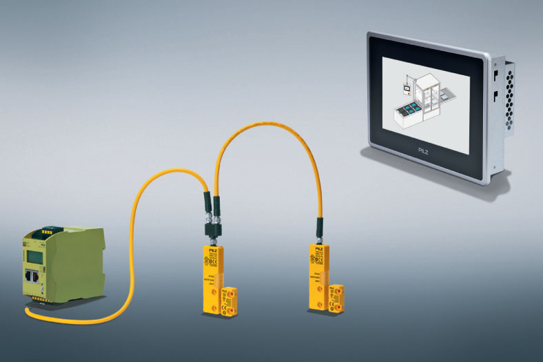
Owing to the diagnostic solution consisting of a fieldbus module as well as a distributor and safe sensor technology, the tried-and tested principle of series connection can for the first time also be implemented in a low-cost daisy chain configuration with safety devices from various manufacturers. In addition, this system – if the sensors of the system are used – also supports diagnostic functions that can optionally be activated depending on the requirements of the processes. This gives the plant operator a high level of flexibility. A standard cable is all that is needed to connect the sensors. Furthermore, depending on the application scenario, passive cabling aids with protection type IP67 or IP20 are available which enable optimum solutions for installation in the field and in the control cabinet.
Smart sensors offer a wider range of functions
Because the diagnostic information in this case can run up to 300 bytes – compared with 1 bit previously – it is possible to realise functions that until now were the preserve of highly complex sensors and programmable logic controllers. E.g. individual serial numbers, the version status, current conditions and also historical fault conditions. This and other data and information is now on the sensor. The sensor makes available exactly that data and information that the user currently requires. For example, users could choose between a highcoded switch and a coded switch using diagnostic information. Both provide an extremely high degree of protection against tampering: If the user opts for a high-coded switch, the protection is permanently and rigidly implemented in the switch. However, users are now able to transfer some data of the coded switches easily to the memory of the control unit where they can then flexibly “replicate the highcoded switch”.
Status monitoring locally and over the Internet
There the data can be queried and processed via Modbus or Profibus and in future also via Profinet or Ethernet/IP. It is then presented neatly on the display of the fieldbus module, the monitor of a PLC or – via web server – on a computer screen. In other words: The data is available to the operator of the machine and also via remote access. The diagnostic solution is configured for the connection of up to sixteen safety sensors, whereby the architecture of the safety circuits is of no relevance. A diagnostic interface can therefore be used for the safety sensors e.g. on the left and right side of the machine, whereby these sensors can each be processed separately by a safety evaluation device. In this way, all sensors can be managed centrally from a mastergate in the diagnostic system, making it significantly easier to monitor several safety devices. Depending on how the network structure is configured, the mastergate can be connected either via DHCP (Dynamic Host Configuration Protocol) or via a previously defined IP address. This provides users with a great degree of freedom with regard to the integration of their existing application into the network.
Single-cable solution for even the biggest of applications
Which diagnostic information can be recorded? Firstly the state of the safety sensors as well as the condition of their inputs and outputs. It is also possible to read out overvoltage or undervoltage warnings that may occur especially with long cables if they were not carefully measured beforehand. This is because, unlike other systems, the innovative diagnostic solution can extend for a total of 900 m, enabling it for the first time to connect up e.g. large high-bay Page 4 of 8 warehouses, intralogistics applications or spread-out facilities in the steel industry by a single-cable solution.
Clear identification of faults
Furthermore, device properties such as the article number, product version number and the serial number can also be called up or equipment identifiers can be stored, which makes replacement easier in the event of a fault. This information is also helpful for swiftly locating a defective safety sensor in complex facilities. In addition, the fieldbus module of the diagnostics solution documents all status changes, even after a voltage reset. This allows faults to be clearly identified, which is not the case using the LEDs of safety sensors. This is important because during the course of repair work other faults can easily occur, e.g. as a result of disconnecting plugs, whereby it may then no longer be possible to detect the original fault. In brief: The diagnostic solution ensures that systems can be put back into operation more quickly.
As a further benefit, warning lights in a control cabinet can be energised directly if a safety sensor has opened a safety gate. This method is still widely used in safe automation. The fieldbus module of the diagnostic solution supports direct actuation of up to six lamps, which reduces the engineering and programming requirements for visualisation. This means that the plant operator benefits from simple cabling in the field, but still knows exactly which gate is affected.
Guard locking can now be performed individually
In conjunction with the secure safety gate system PSENmlock, it is now also possible to energise safety gates individually with the diagnostic solution despite the extensive single-cable solution. If, for example, maintenance work or a tool change is pending in a system, it is possible to define which gates are allowed to be opened after the shutdown – all gates would open if Safety Device Diagnostics was not used – and who has access authorisation. This ensures that only personnel with the appropriate training and authorisation access the system, thereby preventing tampering attempts or data theft on site.
Documentation of changes minimises downtimes
As the diagnostic solution enables a wide variety of diagnostic data to be collected on site or remotely, it can also be used for predictive maintenance, which is increasingly gaining in importance against the backdrop of Industry 4.0. This applies not only with respect to the timely replacement of worn parts, but also for maintaining operational safety. Previously, if an operator was to report a problem years later, it was difficult for the manufacturer to determine what had been changed in the machine in the mean time. Using the data stored in the diagnostic solution, it is now possible to compare the original status with the current status at the click of a mouse – and without the additional hardware that is otherwise needed at control level. This again helps to shorten downtimes.
Diagnostic solution supports modular approach
Another example of Industry 4.0 scenarios are intelligent solutions for the functional safety of modular systems. By daisy chaining the diagnostic solution, it is relatively easy for the mechanical engineer to add a further module. If, for example, customers want to not only manufacture their products but to also foil-wrap and package them, no new cabling is required, it is not necessary to make modifications in the control cabinet and to the design plans and no additional Page 6 of 8 safety devices are required. Apart from the electric circuit, all that is required is for the safety sensors to be installed for the right and left safety gate for each module and connected via a further distributor to the last sensor in the daisy chain. An additional fieldbus module is only necessary if 16 sensors are already connected to the diagnostic solution. In the majority of cases, however, no more than six, eight or at most ten sensors are connected in series, making this configuration more than adequate.
Alternative approach: IO-Link Safety
The entire function range of the diagnostic solution is available if all components are used. IO-Link Safety is an alternative approach that is currently being developed. It guarantees interoperability down to the sensors and therefore functions on all levels with safety devices from different manufacturers. Data is transmitted safely from the sensor to the PLC, which opens up new application possibilities. With IO-Link Safety, it is the PLC that switches and not the sensor, whereby expensive safety architectures are emulated and new interdependencies between sensor and PLCs (e.g. in the event of replacement) arise. Furthermore, this approach is based on pointto-point connections, i.e. on a star configuration, in the field or in the control cabinet. All in all, both the installation and engineering costs are considerably higher than for the diagnostic solution because not only the cabling requirements increase, but also safe PLCs are necessary in order to evaluate the data of the sensors. You don’t need to be a prophet to predict that sooner or later there will be two diagnostic systems. Depending on the application, the cost-benefit ratio will be the primary factor in deciding which system will gain acceptance. At present, IO-Link Safety is still a vision of the future. The SDD diagnostic solution, however, can already be used today.
A diagnostic solution like Safety Device Diagnostics significantly reduces the number of service calls thanks to its detailed and more conclusive diagnostics. Clearly visualised information both on site and via remote access is provided.
Furthermore, the clever single-cable solution extends the boundaries of series connection: The innovative series connection for safety sensors and the direct evaluation of data from the sensor not only significantly increases availability. Through its modular approach, it also presents a suitable diagnostic solution for the factory of the future.
For more information, visit www.pilz.com
Cookie Consent
We use cookies to personalize your experience. By continuing to visit this website you agree to our Terms & Conditions, Privacy Policy and Cookie Policy.






 English
 Hindi
Hindi