Revolutionising the art of Die making
December 15, 2016 11:50 am
The changing face of technology has sparked a revolution in the area of die making. Technologies like Tebis and Vericut have been in the forefront of changing die making industry. A look at these technologies.
Emerging die and mould technologies
The rise of newer technologies in the die and mould sector will change the course of manufacturing of dies and moulds. Here are two upcoming technologies that will have a lion’s share in revolutionising die making.
Tebis –making efficient usage of time
Tebis, the software and process provider for the development, design and manufacture of models, moulding tools and components, has made its Version 4.0 Release 3 available on the market in the fall of 2016. In its update to Version 4.0, Tebis has focused on a more efficient use of time. Among other measures, the software achieves this by automatically breaking up assemblies and complex files with many manufactured parts into multiple individual files. The user can immediately access the corresponding component with no effort at all.
With Release 3, Tebis has also improved the display of wire-frame models and isolines. The user is often confronted with the problem of many isolines, which can make the view of the components unclear on the screen. The colours of the models can be adjusted independently of the surface colour in the new Release 3.
With this update of the proven CAD/CAM software, customers will be able to design their processes more efficiently: The newly added functions allow users more flexibility and cost efficiency in design manufacturing preparation and processing, saving them considerable time. This is supported by more intuitive and simpler operation.
Toolbars and menu panels can be easily docked to the edge of the application window. The software interface is more informative for the user, who can learn to operate it more quickly and easily and with less effort. A new project dialog with the most recently used files is displayed immediately after the program is started, so the user won’t lose any time after an interruption.
This is supplemented by preview images of saved components.
The new Version 4.0 also delivers customers improved reliability in NC programs. An extended list with known machine conflicts is integrated in the CAD/CAM software for quick access by the user. This enables users to mark and filter acceptable and critical conflicts between the affected machine components. Release 3 provides an additional option for automatic collision avoidance in 3-axis milling.
The NC automation of 2.5D drilling and milling is also more efficient, because the processing sequence in feature-based NC programming can now be more easily influenced by feature groups. Tool optimization has also been extended in the Job Manager. Tools can be changed across machining operations in NCJobs. The user can also assign NC variables across features. Standard and free-form functions can be selected independently of type and parameter assignment. The software always identifies currently different and modified variable assignments.
The new release also includes a function that is perfect for engraving texts, logos and numbers. The operator receives a text that is projected on the component geometry. A new function has been incorporated to calculate the 5-axis toolpath required for this operation.
The user can shorten cycle times by roughly 30 per cent in laser cutting and trimming. This is because the improved NC point distribution results in more compact programs. The user can set axial tolerances and manually remove NC points. In Release 3, head tilt directions on the manufacturing machines can also be handled more easily in stamping areas. This prevents rapid pivot movements of the machine. The toolpaths can be checked numerically with the ‘Collision check machine’ add-on, so that collisions and limit-switch conflicts never even occur. This saves more time and costs.
VERICUT Composite Applications Software Version 8
CGTech is now shipping the next major release of VERICUT Composite Applications: VERICUT Composite Programming (VCP), VERICUT Composite Simulation (VCS) and VERICUT Composite Paths for Engineering (VCPe). VERICUT Composite Applications are being used by leading manufacturers to program and simulate automated fibre placement and tape-laying machinery from machine tool builders such as, Electroimpact, MTorres, Fives, BA Composites and others.
“With a specific focus on closing the design for manufacturing loop, we’ve added powerful new features to help our customers build parts that meet their specifications and run on their machines,” said Product Specialist Charles Anderton. “Version 8.0 optimizes workflow and helps users find the functionality they need with a minimum number of mouse clicks.”
Many new features have been added in version 8.0, that include enhanced support for AFP or ATL hybrid machines, more ways to utilize laser inspection data, display detailed scrap calculations, and other vital analysis tools.
VCPe gives the user the ability to measure and evaluate the effects of AFP and ATL path trajectory, material steering, surface curvature, course convergence and other process constraints as they would be applied in manufacturing. The software also provides prodcutability analysis of the fiber angle based on the curvature of the part, and overlap and gaps needed for structural analysis. Tape course geometry can be written to various CAD formats for further evaluation by the user’s existing analysis methods and tools.
VCP reads CATIA V5, STEP, or ACIS surface models. It also reads Fibersim, CATIA V5 or other external ply geometry and information. VCP then adds material to fill the plies according to user-specified manufacturing standards and requirements. The layup paths are linked together to form specific layup sequences and are output as NC programs for the automated layup machine.
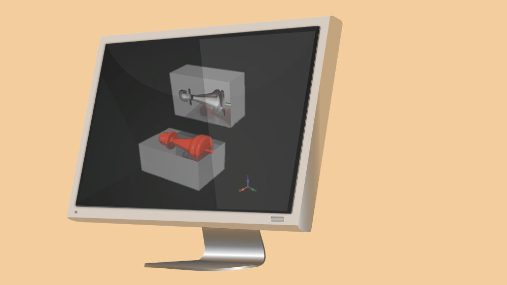
VCS reads CAD models and NC programs, either from VCP or other composite layup path-generation applications, and simulates the sequence of NC programs on a virtual machine. Material is applied to the layup form via NC program instructions in a virtual CNC simulation environment. The simulated material applied to the form can be measured and inspected to ensure the NC program follows manufacturing standards and requirements. A report showing simulation results and statistical information can be automatically created.
Latest offerings in this domain
Fibro India Precision Products Pvt. Ltd has come up with a new product, Mould Line, the gas spring for mould making. Speaking about the product, Ramkrishna Edara, AGM Business Development, Fibro India Precision Products Pvt. Ltd says, “Gas springs are always the right choice whenever, for instance, another intermediate plate or a slide unit is to be moved parallel to the mould opening at the parting line.”
Speaking about the advantages of Mould line gas springs, Edara says, “When it comes to Mould Line, minimal adjustment is required and there is no need for lubrication. Mould line gas springs require no maintenance for up to 500,000 strokes and have variably adjustable forces. The mould temperatures can go up to 120°.” The design of Mould Line is approved as per the European Pressure Equipment Directive 97/23/EG. A pressure monitoring system makes it possible to recognise an impending failure at an early point. The company claims in all cost savings of 60 -70 per cent versus a latch lock.
____________________________________________________________________________________
Gas springs are always the right choice whenever, for instance, another intermediate plate or a slide unit is to be moved parallel to the mould opening at the parting line.
Ramkrishna Edara, AGM Business Development, Fibro India Precision Products Pvt. Ltd
Cookie Consent
We use cookies to personalize your experience. By continuing to visit this website you agree to our Terms & Conditions, Privacy Policy and Cookie Policy.
